
Introduction
For a while I used a Netgear Firewall Router as network switch and internet router. An additional Raspi Zero provided a PiHole instance in order to keep the network ad free. Unfortunately the router wasn’t able to provide more than a throughput of 16MBit/s from the LAN to the WAN (which I embarrassingly realized after I held my provider accountable for the slow internet connection ).
Actually I couldn’t find a good alternative for the crappy Netgear router because most devices today only provide 4 LAN ports and I need at least six. So I ordered an eight port switch and started this little weekend project.
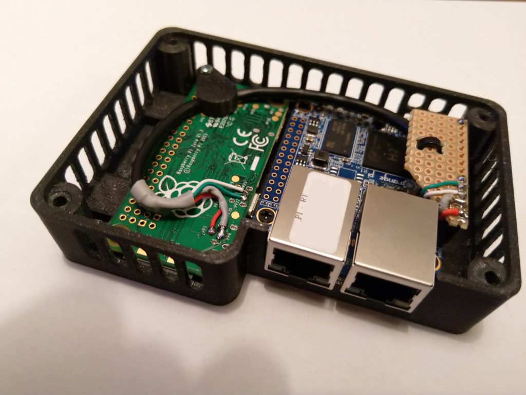
What I wanted was a simple OpenWRT router with one WAN interface and one LAN interface together with an additional Raspi Zero which could be used for other services. This setup allows to play around with the Raspi Zero without influencing the router. In order to keep cabling to a minimum, I wanted to connect the Pi Zero via a USB network connection.
OpenWRT on the Orange Pi R1
The OrangePi R1 is officially supported by the OpenWRT project, unfortunately it doesn’t support the additional USB ports of the board. In order to get USB running with the current version (19.07) you have to compile the sources yourself after hacking a kernel patch. I’m not very familiar with modifying the kernel respectively the Device Tree so I took a quick and dirty approach (..and left a message in the forum, hoping someone will submit the hack as a proper patch 🙂
For now, the hack will do…
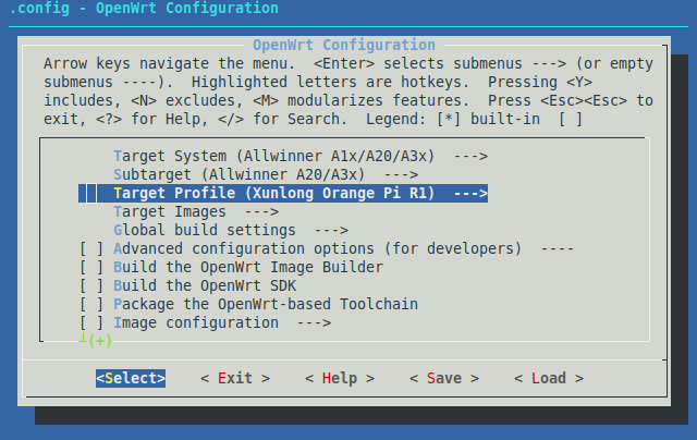
I assume you are running Linux. Download the sources of the OpenWRT 19.07 version from GitHub: https://github.com/openwrt/openwrt/tree/openwrt-19.07 and get your build environment ready according to https://openwrt.org/docs/guide-developer/quickstart-build-images within menuconfig your target configuration should look something like this:
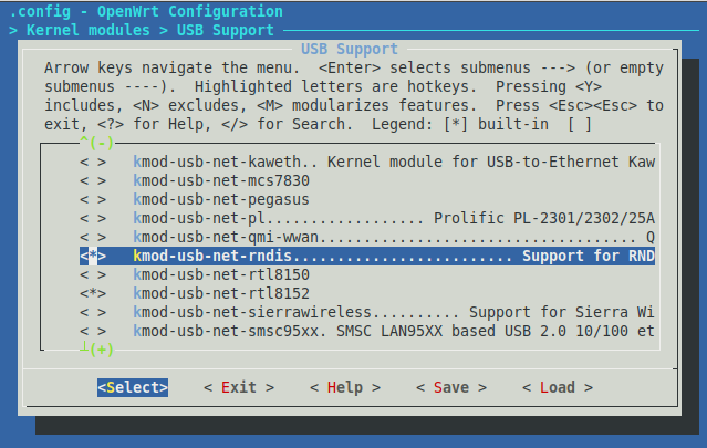
In addition we need the RNDIS driver which can be activated at Kernel modules–>USB Support–>kmod-usb-net–>kmod-usb-net-rndis. If you need anything else, now is the time.
Save the build config and open the file target/linux/sunxi/patches-4.14/201-ARM-dts-sun8i-fix-USB-Ethernet-of-Orange-Pi-R1.patch and replace its content with the following:
From b76dc5927f6442df913f03ed261c5bff18a98df6 Mon Sep 17 00:00:00 2001
From: Icenowy Zheng <icenowy@aosc.io>
Date: Thu, 28 Dec 2017 21:01:56 +0800
Subject: [PATCH] ARM: dts: sun8i: fix USB Ethernet of Orange Pi R1
Orange Pi R1 uses a Realtek RTL8152B USB Ethernet chip, which is easily
seen on the board but not show in the schematics. A regulator for the
power of the RTL8152B chip is hidden, which uses the same pin with the
Wi-Fi regulator on the original Orange Pi Zero.
Add this regulator back to the device tree, and bind it to USB1.
Signed-off-by: Icenowy Zheng <icenowy@aosc.io>
---
arch/arm/boot/dts/sun8i-h2-plus-orangepi-r1.dts | 18 ++++++++++++++++++
1 file changed, 18 insertions(+)
--- a/arch/arm/boot/dts/sun8i-h2-plus-orangepi-r1.dts
+++ b/arch/arm/boot/dts/sun8i-h2-plus-orangepi-r1.dts
@@ -49,6 +49,20 @@
/delete-node/ reg_vcc_wifi;
+ /*
+ * Ths pin of this regulator is the same with the Wi-Fi extra
+ * regulator on the original Zero. However it's used for USB
+ * Ethernet rather than the Wi-Fi now.
+ */
+ reg_vcc_usb_eth: reg-vcc-usb-ethernet {
+ compatible = "regulator-fixed";
+ regulator-min-microvolt = <5000000>;
+ regulator-max-microvolt = <5000000>;
+ regulator-name = "vcc-usb-ethernet";
+ enable-active-high;
+ gpio = <&pio 0 20 GPIO_ACTIVE_HIGH>;
+ };
+
aliases {
ethernet1 = &rtl8189etv;
};
@@ -71,3 +85,23 @@
reg = <1>;
};
};
+
+&usbphy {
+ usb1_vbus-supply = <®_vcc_usb_eth>;
+};
+
+&ohci2 {
+ status = "okay";
+};
+
+&ohci3 {
+ status = "okay";
+};
+
+&ehci2 {
+ status = "okay";
+};
+
+&ehci3 {
+ status = "okay";
+};This simply enables the additional USB ports. Save the file and start to compile using make -j. Now its time for a coffee break.
If everything worked you should now find an image for your Orange Pi R1 in bin/targets/sunxi/cortexa7. Dependent on your preferences you can decide to use either openwrt-sunxi-cortexa7-sun8i-h2-plus-orangepi-r1-ext4-sdcard.img.gz or openwrt-sunxi-cortexa7-sun8i-h2-plus-orangepi-r1-squashfs-sdcard.img.gz. Load the contained image to an SD-Card and power up your Orange Pi R1 with it.
It should be possible to connect to OpenWRT using ssh root@192.168.1.1 on the connector without the sticker. The other connector needs to be connected to a DHCP enabled net with internet access. First of all we need to install LuCI (https://openwrt.org/docs/guide-user/luci/luci.essentials for details):
opkg update
opkg install luci
opkg install luci-ssl-nginx
LuCI should now be available via https://192.168.1.1/.
Raspian installation and RNDIS setup
I used Raspbian Buster Lite for my setup, but the following should work on other versions as well.
Obviously, first step is to prepare an SD-Card with the Raspian image. After that we need to activate the ethernet adapter emulation. Open the boot partition and add the following line to the config.txt:
dtoverlay=dwc2Open the cmdline.txt and add the following text behind rootwait:
modules-load=dwc2,g_etherThe last step in the boot partition is the creation of an empty file named ssh in order to allow console access.
For details you might consider reading https://learn.adafruit.com/turning-your-raspberry-pi-zero-into-a-usb-gadget/ethernet-gadget (even if I doubt their choice for a text editor).
Bringing it all together
Connect the Pi Zero to the Orange Pi R1 using the OTG USB port of the Pi Zero (the inner one). If you run dmesg on the Orange Pi it should show something like
[    8.902193] usb 4-1: New USB device found, idVendor=0525, idProduct=a4a2
[    8.908916] usb 4-1: New USB device strings: Mfr=1, Product=2, SerialNumber=0
[    8.916146] usb 4-1: Product: RNDIS/Ethernet Gadget
[    8.921287] usb 4-1: Manufacturer: Linux 4.19.75+ with 20980000.usb
[    8.930453] cdc_ether 4-1:1.0 usb0: register 'cdc_ether' at usb-1c1c000.usb-1, CDC Ethernet Device, xx:xx:xx:xx:xx:xx
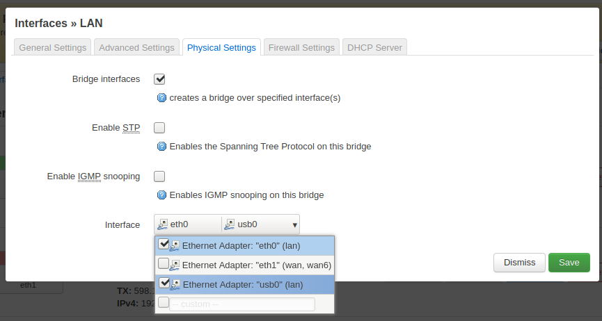
For the rest we can use LuCI. Open Network–>Interfaces and click on Edit at the br-lan interface. Open the tab Physical Settings and activate usb0 in the drop down box on the bottom.
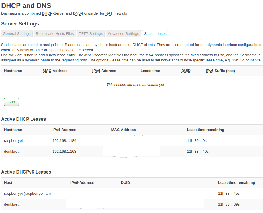
We now have connected the Pi Zero to the 192.168.1.x network. It should be available via raspberrypi.lan or the IP-lease that it got from OpenWRT (see Network–>DHCP and DNS–>Static Leases).
This should be enough to get you up and running. I highly recommend to set a password for OpenWRT as a next step 😉
I hope the same can apply for the new board OPI R1 Plus based on RK3328.
Then add the Sata board, which (I hope) can connect to an USB3.0 port of the RK3328 (fingers crossed)